Translate

Saturday, July 20, 2013

IR Remote Controlled Car (PWM motor control using ATmega8)


Hi Friends,
in my last post of Simple DC motor Control, I've discussed controlling a small DC motor using the PWM method with MOSFET H-bridge. The circuit was build with microcontroller ATmega8.
Here, I'm extending the same circuit to control the DC motor with IR remote control. The motor is fitted on a toy car wheels with gears, as shown in the figure above.

Following is the schematic (Click on the image to enlarge it):

The circuit uses two PWM channels of ATmega8 for controlling the speed and direction (reverse, forward) of the car, based on the command received from the IR remote. Here, a Sony TV remote was used. The IR codes were received by using TSOP1738 IR detector from Vishay. (Thanks a lot to Michael Spiceland from tinkerish.com, for helping me out with the code for IR signal decoding!).

Following buttons on the remote are used for control:
'1' : Start motor
Volume+ : Increase speed
Volume-: Reduce speed
Channel+: Forward direction
Channel-: Reverse Direction
'0': Stop motor

Check out the video (the LED blinks whenevr a key on the remote is pressed. The remote is not visible in the video as I was holding the camera and remote both!!)
--------------------------------------------------------------------------------------------
The coding is done with ICCAVR compiler. It can be easily adapted to other compilers with minor changes. Complete code is given here:

View Code on Google Docs
Download source code files (zip)

Download datasheet & further info:
TSOP1738 datasheet
Info on Sony remote control codes

Digital Automatic Gain Control Agc

 This project is a digital Automatic Gain Control (“AGC”) system using a PIC16F876 MCU. The ability to set the gain level in a circuit and have it control itself is a very useful function. This circuit is a building block of another project I am working on. A 30W power amp for either the PCS, iDEN or CDMA frequency bands. I will settle on one of those frequencies sometime soon.

Theory of operation: I needed to control the gain so the signals for a digital downconverter (DDC) and digital upconverter (DUC) would be in a specific range so the A/D that processes the IF of the mixers does not get over-driven by the amplitude of the input signals. Using a digital attenuator, logarithmic detector / controller, and a MCU with an A/D converter I was able to accomplish this task fairly easy with minimal components.
-----------------------------------------------------------------------------------------------------
System Operation: The heart of this AGC system is the  AD8313  logarithmic detector / controller. It is a demodulating logarithmic amplifier that converts an RF signal to an equivalent decibel-scaled value of DC at its output. The RF input is sampled by the AD8313 through a  20dB (TCD-20-4) coupler. The The AD8313  is connected to the  PIC16F876  A/D via an op-amp configured as a voltage follower. I used a 4.096VDC as the reference voltage giving me a step size of 4mV since the A/D is 10-bits. If the A/D reading is too high it starts turning on attenuators to decrease gain. If the signal is too high, the attenuators are turned off. I placed a red LED and a green LED in the circuit for when the signal is too low or too high (face it, everybody likes to see LEDs light up!). When the input signal is too low, the red LED is on. While the signal is too high, the green LED comes on. If the signal is within tolerance, both LEDs are off. The  HMC273MS10G digital attenuator has a max attenuation of 31dB with increments in steps of 1dB. The amplifier used was a  SGA-6389 SiGe HBT MMIC amplifier. The gain on this amplifier was roughly 14dB and provided a IP3 of +35dBm.


          FIRMWARE:       View .C (CCS PCW) file.


Future Use: The  PIC16F876 has 8K of FLASH as well a bunch of I/O and A/D channels left for other operations. I may even use the USART of the PIC to be able to control the gain of the system via RS232. Could attatch a temp sensor to control the temperature of the overall assembly. If the amplifier gets too hot, turn a fan on. Or even use the AD8313 as a power meter of sorts. There are so many ideas I don’t want to list them all!!! Special note: Many THANKS goes out to Dale Botkin and Edson Brusque for suggestions with the CCS compiler!! This code as well as the little bit of schematic provided can be used as you wish. If you find it useful don't hesitate to drop me a line, I would love to hear about the uses of the AD8313 or PIC in AGC systems that other people have done.

Solar Powered Robot Known as Smiley

 Smiley draws power from the little solar panel on top. His motors are clocks, modified to run considerably faster than normal. The wheels are of a type found on model aircraft landing gears. He feels his way around with 0.3 mm steel wires, bent to form quarter circles.
Smiley's behaviour is based on three rules:

If no feeler switches are closed, the motors will obey the `eyes'. Smiley moves towards the best light, while trying to avoid shadow patches.
If one of the feelers touches an obstacle, Smiley "follows the wall" in the direction of the better light. Both this and the first behaviour are illustrated here.
With both feeler switches closed, the robot will push against one of them, trying to get free.
My other solar-powered `bots - Photovore, SunEater_III, and Son of Photovore - show exactly the same behaviour. But Smiley is the first to manage with just one IC and one transistor as `brain':
Smiley schematic

Smiley's heart is the generator built around the schmitt-trigger/inverter and the transistor on the right. When the solar panel doesn't get much light, its voltage drops. The generator reacts by lowering its frequency, causing the average current consumption of the active motor to drop as well. At 2V, the frequency is only 0.5Hz. Smiley moves about very slowly, consuming only 75uA. At 2.2V, the frequency is about 5Hz, giving ten times the speed at more than 600uA. Use clocks that audibly tick and you'll hear Smiley work up enthousiasm as the light gets better :)
The maximum you want to reach depends on the clocks you find, as the stepping motors inside won't reliably turn clockwise if the frequency exceeds a certain value. My clocks were good up to about 10Hz, giving twenty times the normal speed. With 57mm diameter wheels on the minute hand shafts, that gives Smiley a top speed of about 6 centimeters a minute. Alright, a snail's pace, but you'll definitly see it move.

The single coil, bipolar stepping motors inside the clocks must be driven directly by the Smiley circuit. The modifications are the same as for my original Photovore, and are shown in detail on this page. If you are using different clocks, you will probably need to experiment with different values for the 47uF driver caps and the 390K resistors in the pulse generator. Note that the red LED must have a forward voltage (measured over the LED when it's on) of 1.4V, at least for the clocks shown.
A schmitt-trigger takes input from the feelers and the BPW41 photo diodes. Thanks to the excellent properties of the BPW41 (don't substitute others unless you know what you are doing), the switch from one motor to the other occurs exactly when a line parallel to the wheel shafts points straight at the brightest light, almost regardless of the light intensity. Smiley moves just like my other light-eating `bots. A series of illustrations shows how it works
PCB layourPCB filmClick on the layout in black to download a version in Postscript. Print it using a laserprinter which understands Postscript (or use Ghostscript) on transparant paper. That makes it very easy to transfer the layout to UV-sensitive PCB material.
Under the hood
Use double-sided tape to fix the clocks on the PCB. Fit heat-shrinkable tubing over the minute hand shafts and merely push on the wheels - if you are as lucky in finding so good a match :)
The hood was made of black paper, attached with bits of double-sided tape.

The photodiodes are mounted below the PCB and look downwards at an angle of about 45 degrees. This keeps them out of direct sunlight and makes Smiley move towards better light while trying to avoid shadow patches                                                        Bottom viewUnhappy


Electronic Stethoscope

Schematic for Electronic Stethoscope
Parts

Part
Total Qty.
Description
Substitutions
R1 1 10K 1/4W Resistor
R2 1 2.2K 1/4W Resistor
R4 1 47K 1/4W Resistor
R5, R6, R7 3 33K 1/4W Resistor
R8 1 56K 1/4W Resistor
R10 1 4.7K 1/4W Resistor
R11 1 2.2K to 10K Audio Taper Pot
R12 1 330K 1/4W Resistor
R13, R15, R16 3 1K 1/4W Resistor
R14 1 3.9 Ohm 1/4W Resistor
C1, C8 2 470uF 16V Electrolytic Capacitor
C2 1 4.7uF 16V Electrolytic Capacitor
C3, C4 2 0.047uF 50V Metalized Plastic Film Capacitor
C5 1 0.1uF 50V Ceramic Disc Capacitor
C6, C7 2 1000uF 16V Electrolytic Capacitor
U1 1 TL072 Low Noise Dual Op-Amp
U4 1 741 Op-Amp
U5 1 LM386 Audio Power Amp
MIC 1 Two Wire Electret Microphone
J1 1 1/8" Stereo Headphone Jack
Batt1, Batt2 2 9V Alkaline Battery
LED 1 Red/Green Dual Colour Two Wire LED
SW 1 DPST Switch
MISC 1 Stethoscope head or jar lid, rubber sleeve for microphone, board, wire, battery clips, knob for R11

Friday, July 19, 2013

Digital Clock with Arduino and DS1307


ds1307 ICIn this article you will learn how to make a digital clock using Arduino and the DS1307 RTC IC. What is DS1307 IC actually? Well, it is a Real Time Clock (RTC) IC that is simple to use, low cost and easy available. The IC basically is able to count the date and time accurately and it will continue its counting if the backup battery – coin cell battery is there although the mainsupply to the IC is cut off.


Part 1 : Demo Video


This video basically just show on a basic role of a digital clock that can display date, time and day of the week.

Part 2 : Hardware

In this part, I will roughly explain about how you can get started to have your own DIY digital clock!

Step 1

The hardware that you need for this are :

DS 1307 RTC IC x 1 – datasheet
32.768kHz Quartz Crystal X 1
Coin cell CR2032 & the holder
10k resistor x 2
LCD board x 1
Arduino x 1
This is the backup battery(CR2032) and its holder. Easily available in any electronic store.
cr2032 holder

cr2032 holder

Step 2

Ok, let’s get started. First of all, connect the DS1307 circuit as below:
ds1307 circuit diagram

ds1307 circuit diagram

So, it is not necessary to use coin cell battery as the backup battery. You can use any type of battery with volatge range from 2.0V to 3.5V as shown above. However, we choose to use coin cell battery as it is small and easy to carry/install.

Warning!
Remember not to connect supply voltage of more than 5.5V or else you will get the chip burnt.

Two 10k pull up resistor s are at the SDA and SCL pins. This is due to the reason that DS1307 communicates through I2C interface.

SDA – Arduino pin A4
SCL – Arduino pin A5
Next, wire up the LCD according to the schematic below:

arduino digital clock lcd

The R3 value normally to be 220 ohm/330 ohm as a current limiting resistor.

Part 3: Software

The software required: Arduino IDE

There is a pretty easy to use library for this purpose. The name of the library is RTClib which you can download it here: RTClib

This library is easy to use and able to get the date, time and day of the week accurately. I bet you will like it when you try it :)

After that, I uploaded the below coding to my arduino UNO. What this code do is basically just set the time and date according to when the sketch is compiled. It might have some slight delay. Then the set date, time and day of the week will be displayed on a LCD screen. In my case, I am using a 20 x 4 LCD screen.

digital clock Arduino sketch
digital clock sketch

Part 4: Pictures
digital-clock-photo diy-ds1307-arduino-module ds1307-pcb

 digital-clock-photo diy-ds1307-arduino-module ds1307-pcb
Part 5: Problems Encountered

Problem 1

When I first trying the new library, the example given only can display date and time and it does not mention about how to display the day of the week. So I started to search on the web and ask in arduino forum about this. You can refer to my thread for more discussions.

So, after some research done in the net, I have finally come to a conclusion. To display day of the week, you can use the below syntax:

int dayofweek = now.dayOfWeek();
   switch(dayofweek){
     case 1:
     lcd.print("Monday");
     break;
     case 2:
     lcd.print("Tuesday");
     break;
     case 3:
     lcd.print("Wednesday");
     break;
     case 4:
     lcd.print("Thursday");
     break;
     case 5:
     lcd.print("Friday");
     break;
     case 6:
     lcd.print("Saturday");
     break;
     case 0:
     lcd.print("Sunday");
     break;
The syntax ‘ now.dayOfWeek();’ will give the day of the week in number form, like 0 for sunday, 1 for monday, 2 for tuesday and so on. So, by having the above coding, you can actually convert the output number to string of character for the day of the week. For example when the output number of ‘ now.dayOfWeek();’ = 0, it will display Sunday on the LCD. So as you can see, Sunday is the first day of each particular week.

Problem 2:

Besides, when you first power up the DS1307, the default date and time will be 1/1/2000 0:00 which is not right. So to set the DS1307 to the current time, simply add the line RTC.adjust(DateTime(__DATE__, __TIME__)); to your code as shown in the sample code as attached. Once you have set the time, then comment out this line and upload again. Why? Below example will explain about it:

Lets say you upload and set the time at 2pm. Then u still keep that particular line of code. Then you power on the arduino again at 4pm. But the arduino start the code by adjusting the time to 2pm again. So once u set already, comment that line out and upload again.

Eagle file for schematic & layout (DS1307 RTC Module V1.0)
Hope you are clear about my simple explore about DS1307.

Thanks for reading and hope you enjoy! Do comment if you have any doubt. You can reach me in my facebook, facebook page, website or email.
Thank you :)

OfficeSuite Pro 7 (PDF & HD) 7.1.1237 Apk

OfficeSuite Pro 7 (PDF & HD) 7.1.1237 Apk

 * UPDATED: May 14, 2013
* CURRENT VERSION: 7.1.1237
* REQUIRES ANDROID: 2.2 and up
* CATEGORY: Business
* INSTALLS: 500,000 – 1,000,000
* SIZE: 24M
* PRICE: $14.99


 Details of OfficeSuite Viewer 7 + PDF&HD 7.2.1283:
The world’s No. 1 mobile office today!
# Installed on over 100 million devices in more than 205 countries
# Over 40,000 registrations per day
# No. 1 app in Google Play Business category
OfficeSuite is a universal document viewer for Android enabling you to open, view, print and share native DOC, DOCX, DOCM, RTF, TXT, LOG, XLS, XLSX, XLSM, CSV, PPT, PPTX, PPS, PPSX, PPTM, PPSM, EML, PDF and ZIP files and attachments ANYWHERE, ANYTIME!


Download APK


OfficeSuite Viewer 7 + PDF&HD 7.2.1283 Android

SPB Shell 3D v1.6.4 APK


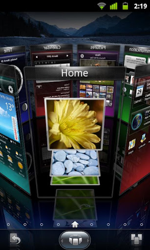
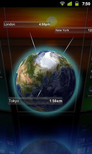
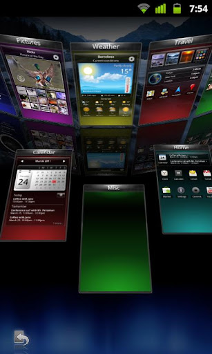
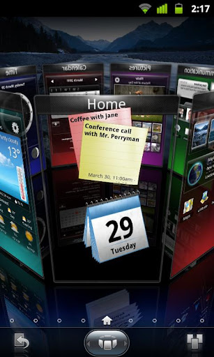
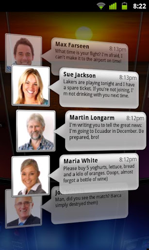
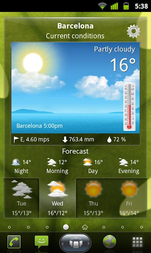
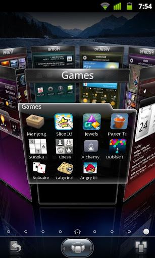
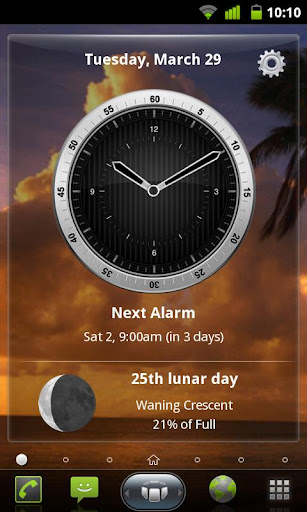
SPB Shell 3D: next generation user interface. Enjoy your phone !


SPB Shell 3D 
SPB Shell 3D: next generation user interface. Enjoy your phone!
If you are not able to launch SPB Shell 3D, please use "Home Switcher" application from Android Market.
Next generation user interface. Enjoy your phone!
To launch SPB Shell 3D press the Home button once installation is completed.


Features:

  • 3D Home screen/launcher
  • Smart folders
  • 3D widgets
  • Collection of panels and widgets
What's in this version : (Updated : May 24, 2013)
  • Minor bug fixes
Required Android O/S : 2.1+


Screenshots :


  Instructions :
  • Install and run with modded Google play by ChelpuS or
  • Remove license verification with Lucky patcher